

Safety and Preparation
Choose the final setup location
Pick the table now
Use the final table with grounded power, ventilation, and reliable internet. Do not build on a temporary surface.
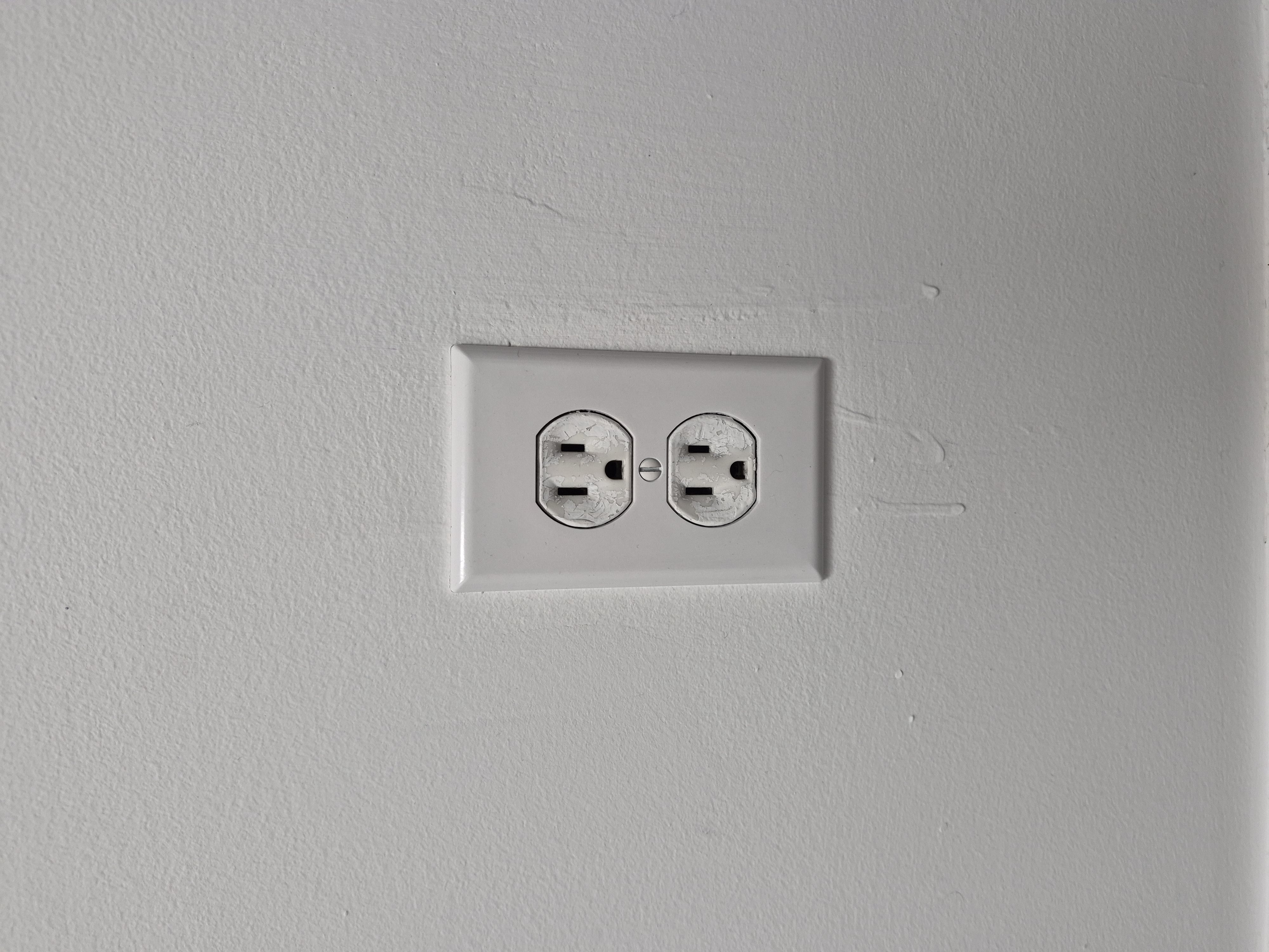
Grounded outlet reference used to confirm the final setup location has the right power available. 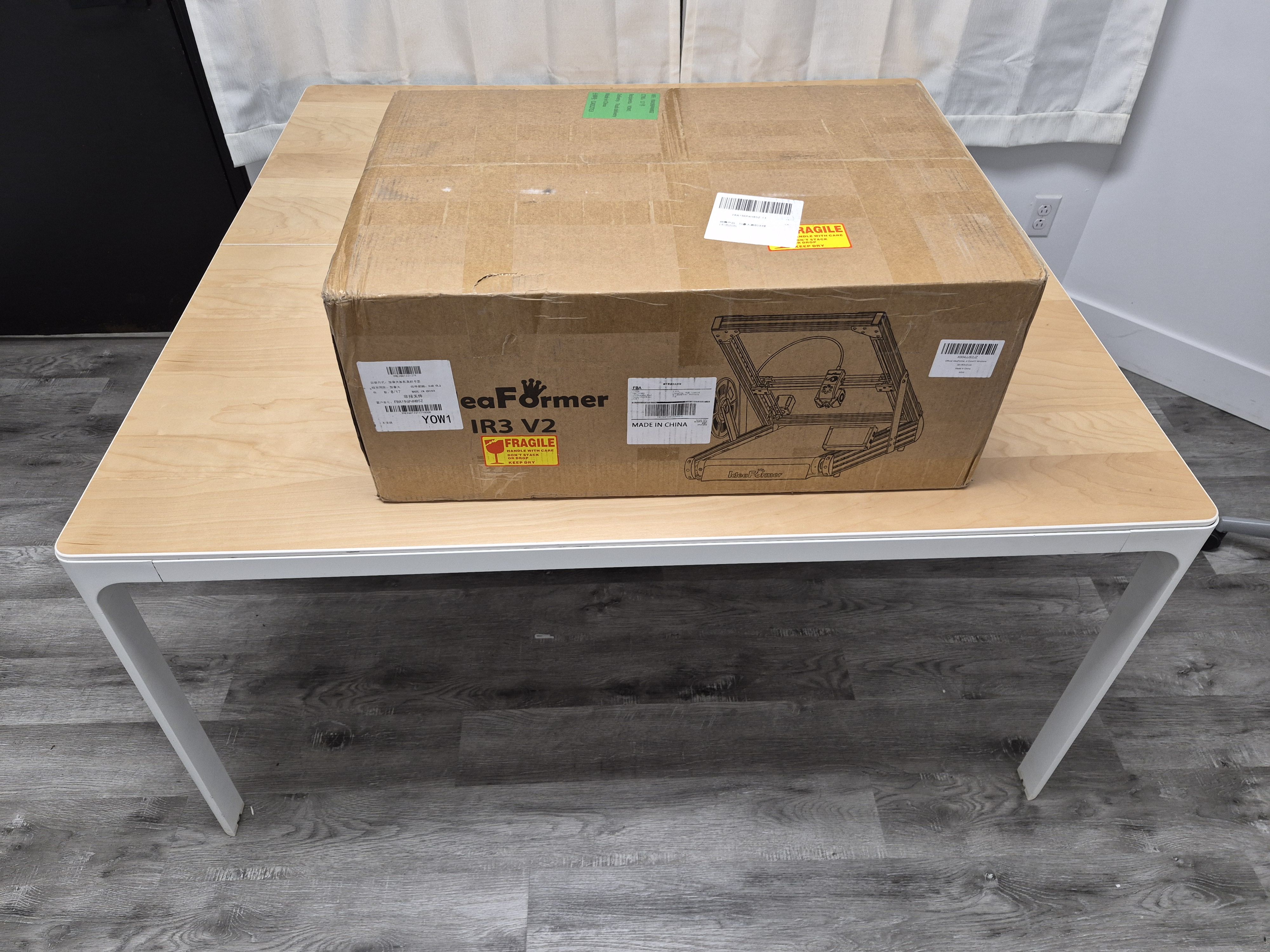
Reference table used to illustrate the kind of clear, stable surface the printer should use from the start. Review the hazards
Hot nozzle and bed. Moving belts and rollers. Keep hands, cables, clothing, and loose items clear.
Keep the Podform3D rules in mind
Keep the screen outside the enclosure. Leave the original SD card in place. Avoid large uploads during prints.
Before you finish
- The final table is selected.
- A grounded outlet is available at that table.
- The operator understands the heat, motion, and Podform3D-specific rules.
Check the kit before assembly
Lay out the main parts
Check the base, frame, baffle, screen, camera, sensor, holder, PTFE tube, tools, and hardware bags.
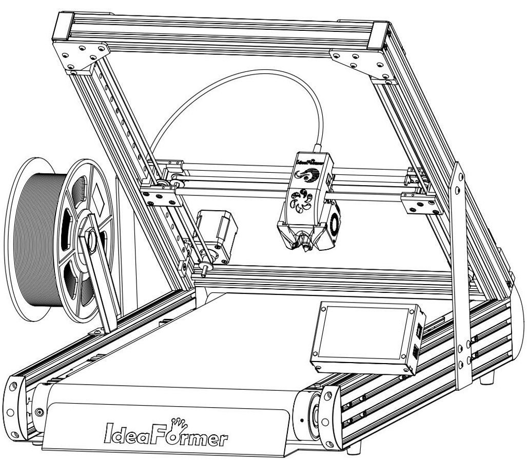
Use the assembled manual overview to name the major parts before assembly starts. 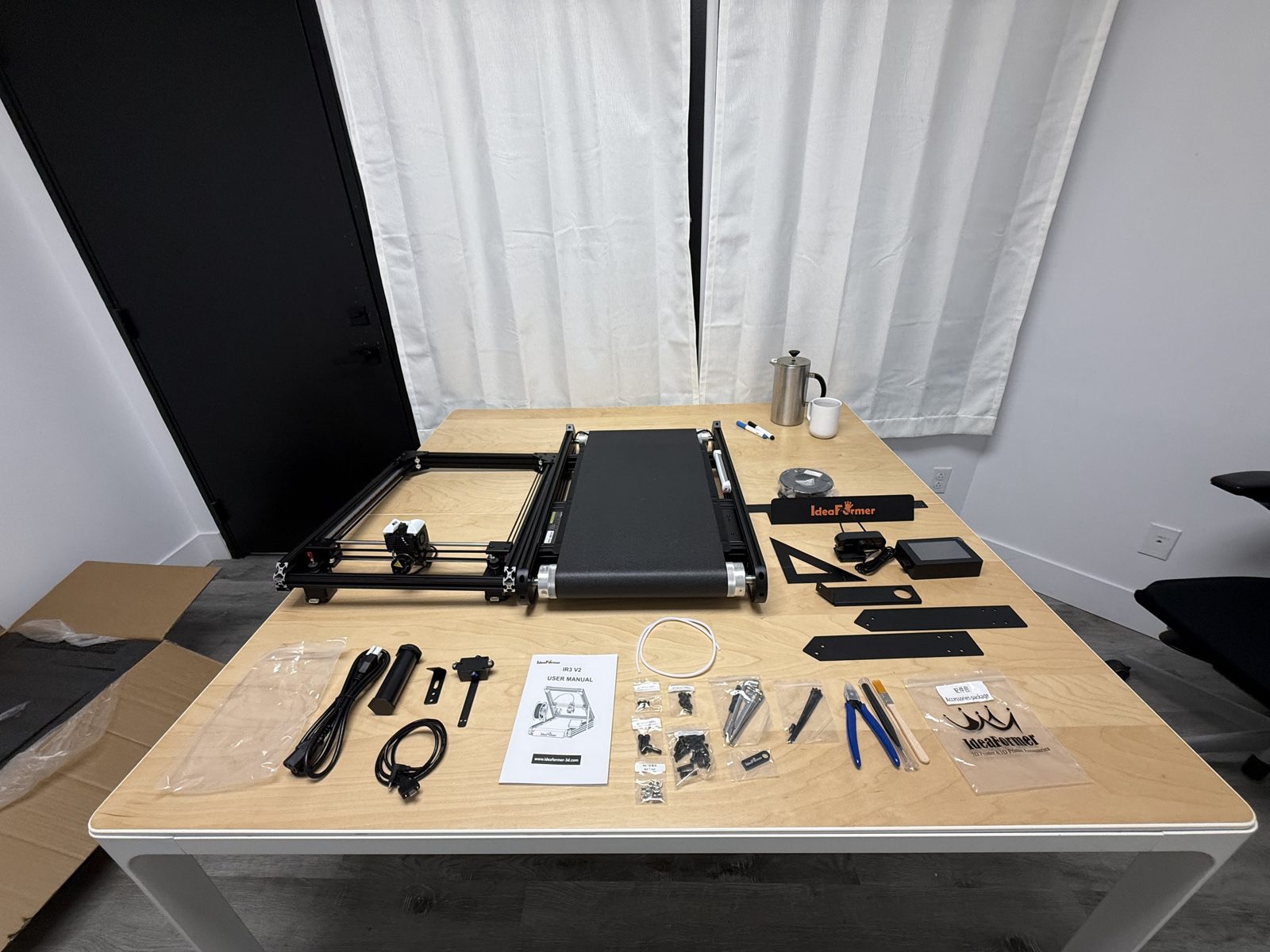
Primary table-layout reference showing the full kit spread before assembly. Check the small parts
Match the screws, brackets, PTFE tube, and tools to the manual before assembly.
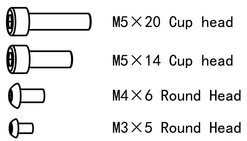
Use the fastener chart when the next steps call for a specific screw family. 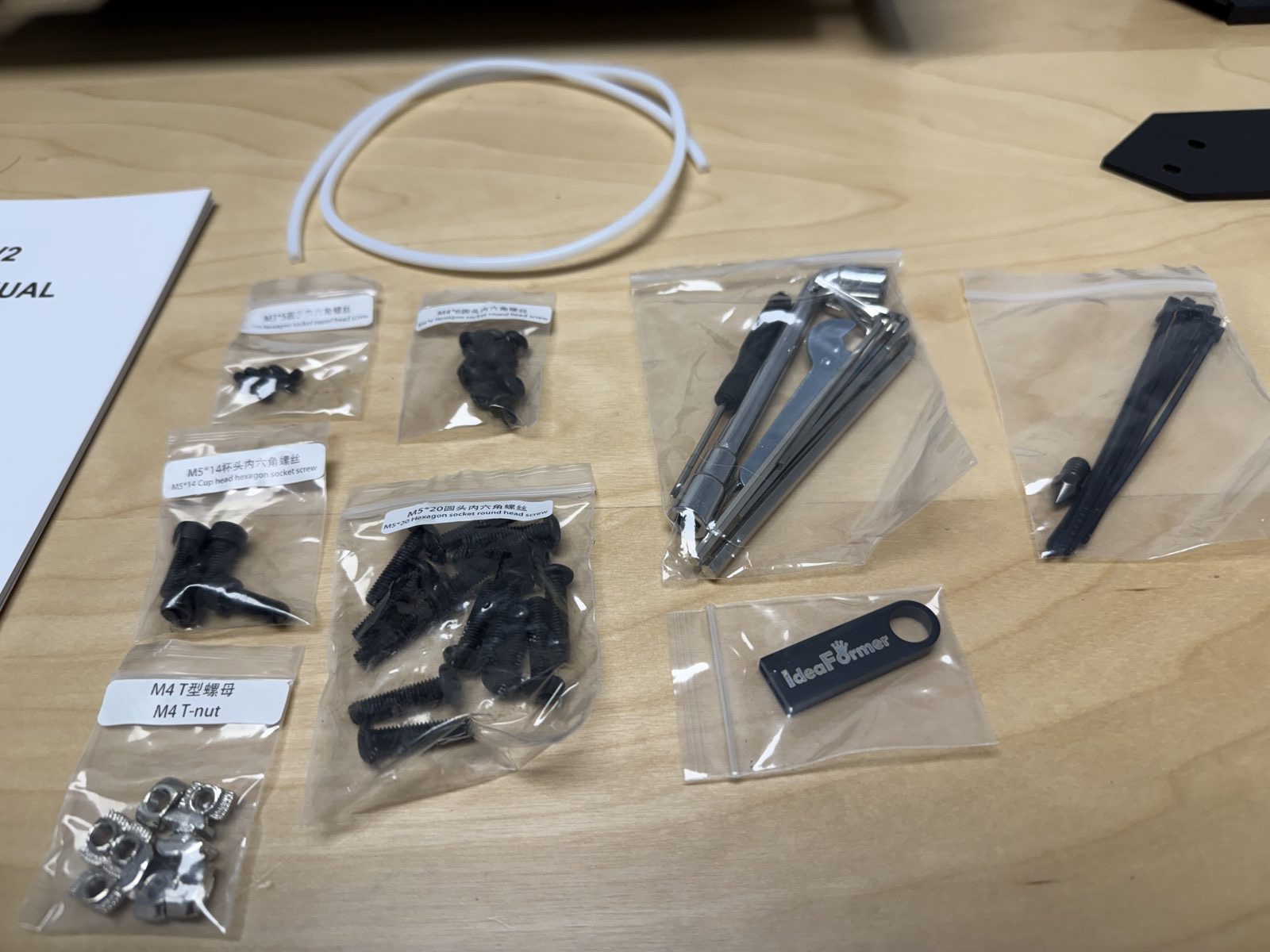
Close-up reference for the smaller parts that are easiest to overlook. Keep the manual beside the table
Keep the IdeaFormer manual beside the table for part names, screw types, and orientation.
Before you finish
- The major assemblies are identified.
- The small parts and screw families are accounted for.
- The IdeaFormer manual is open beside the table.
Mechanical Assembly
Install the front baffle
Position the baffle before tightening
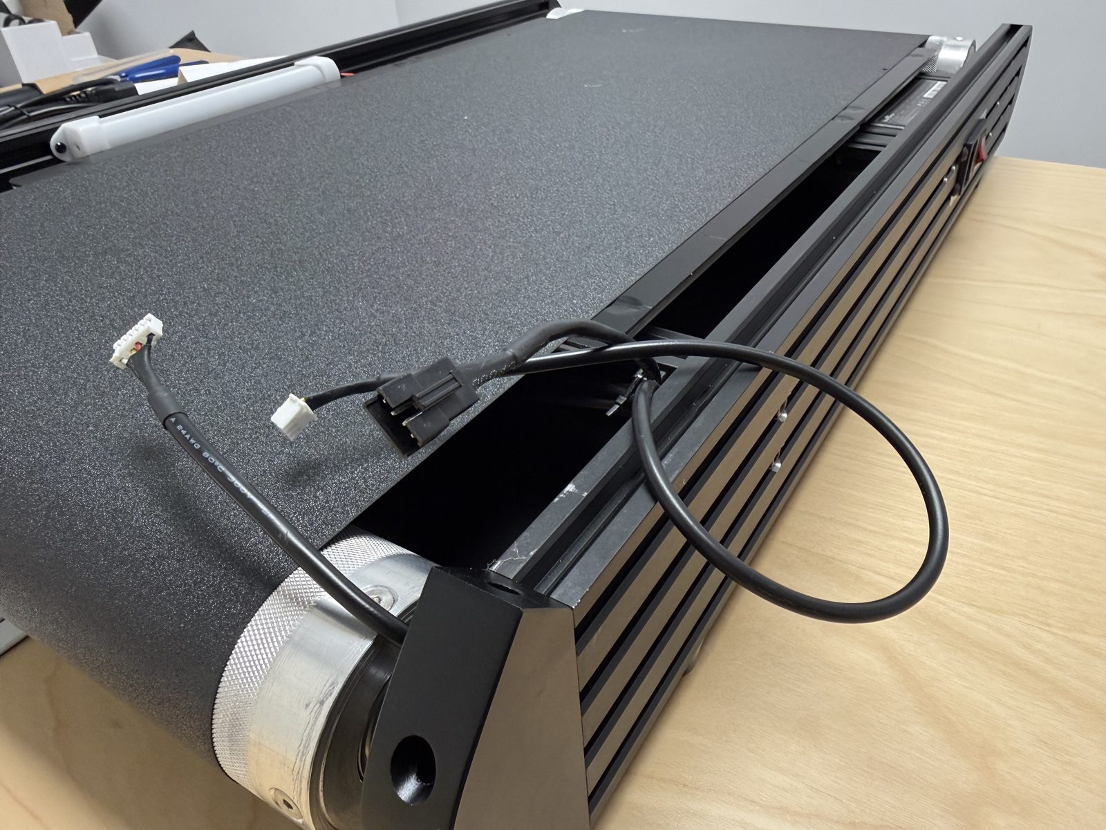
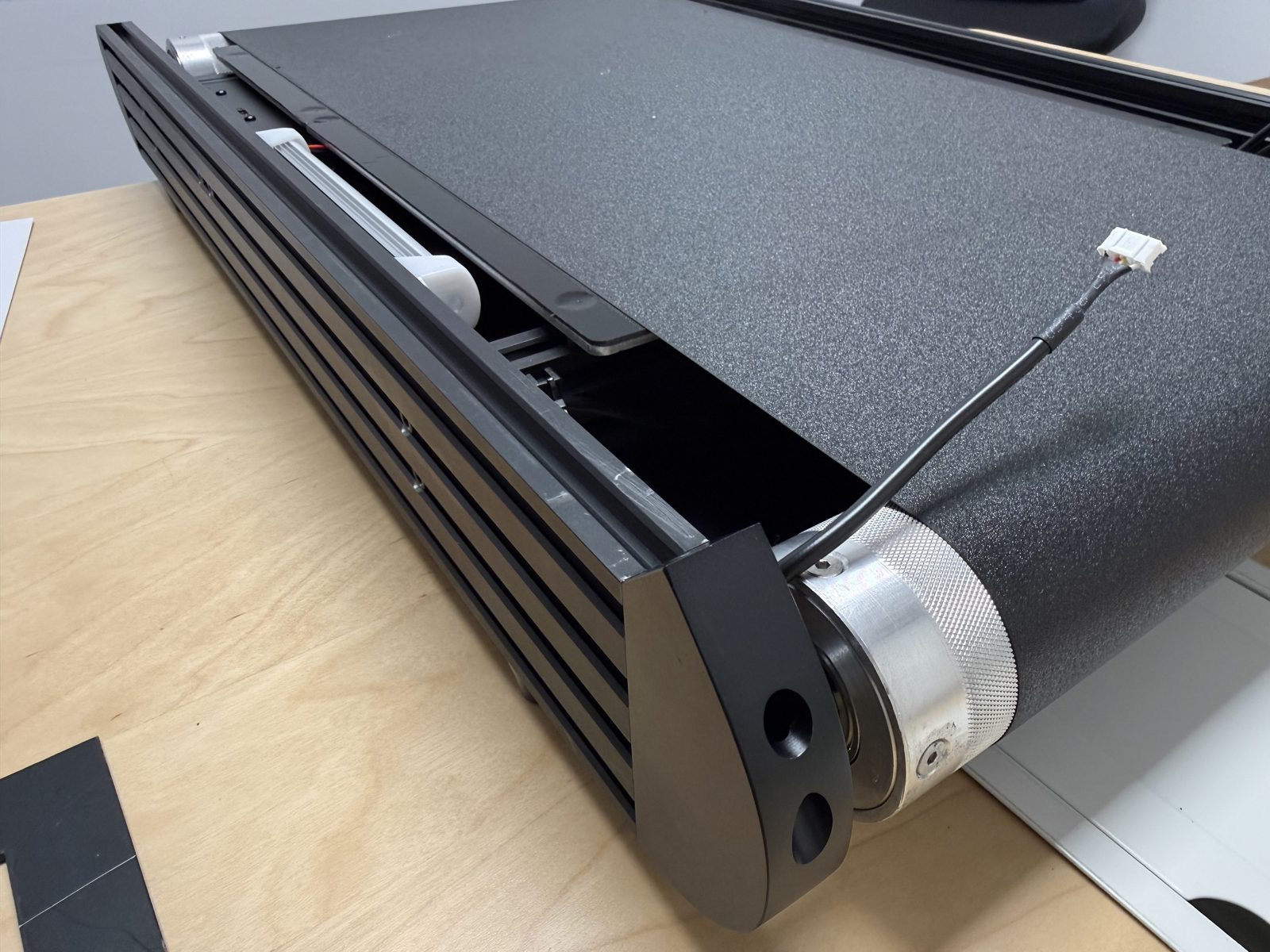
Start the screws, center the baffle, and keep it even across the front.
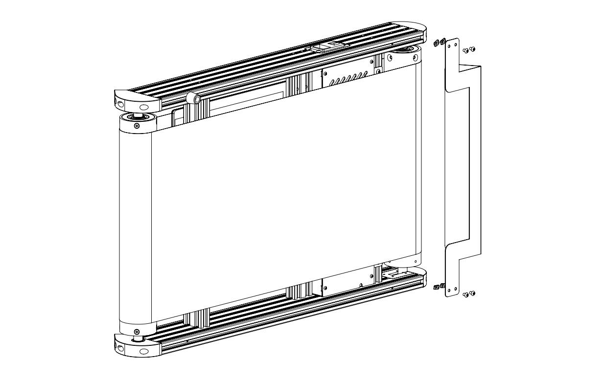
Manual reference for the baffle position and fastener placement. 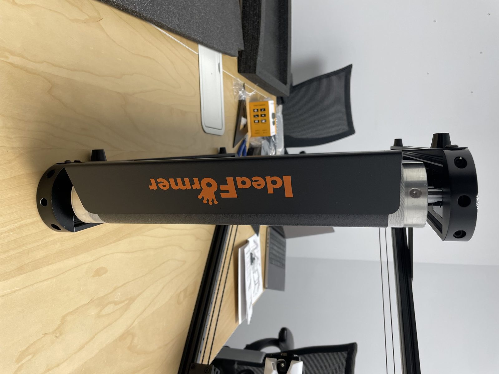
Front reference used to confirm the baffle sits square before the final gap check. Check the gap with paper
Slide one sheet of paper through the gap. There should be no visible gap, and a single sheet of paper should barely pass. If the paper slides freely, the gap is too large. Reposition the baffle before printing.
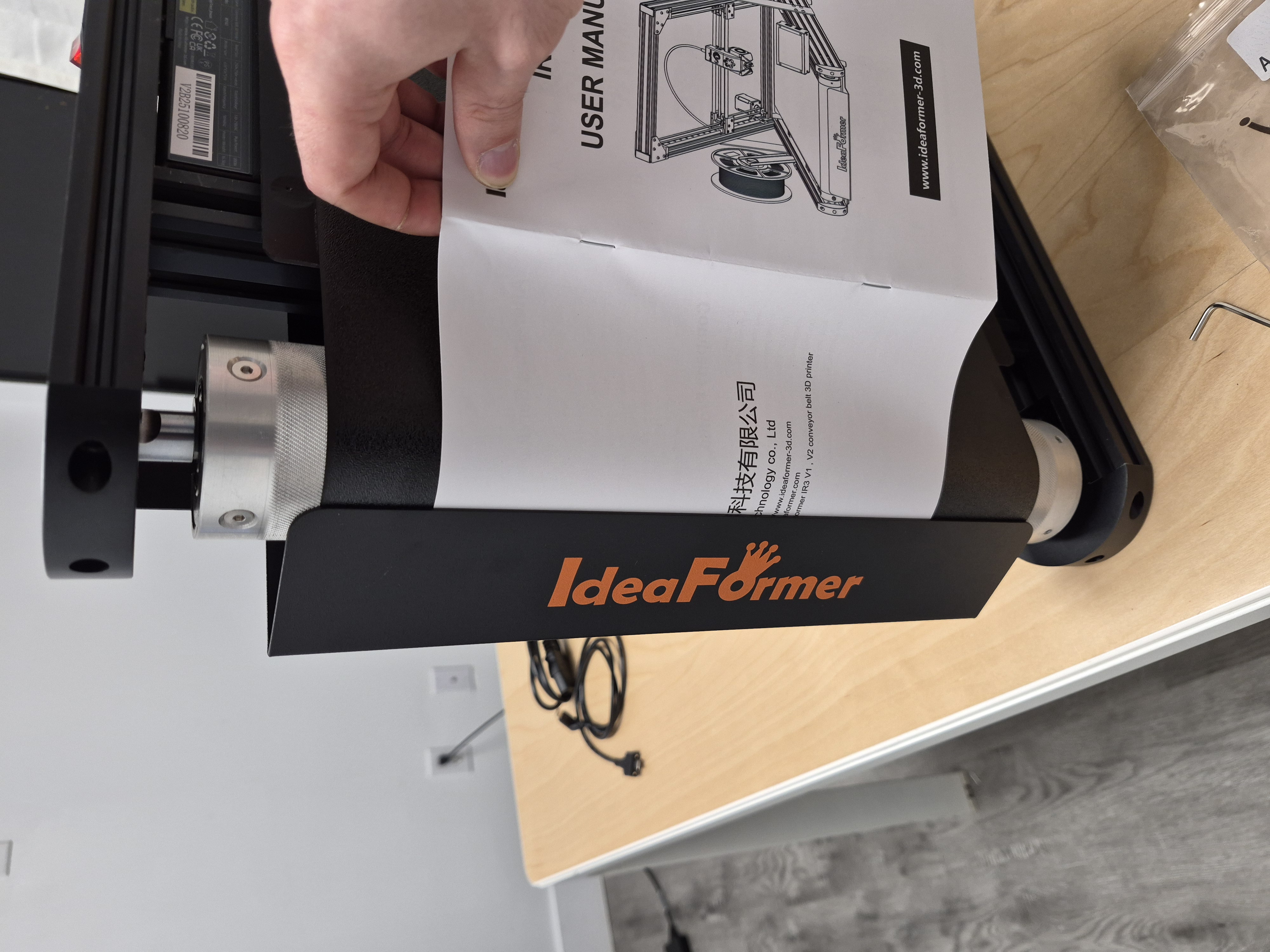
Use one sheet of paper as the gauge. It should barely pass, with no visible opening left at the baffle. 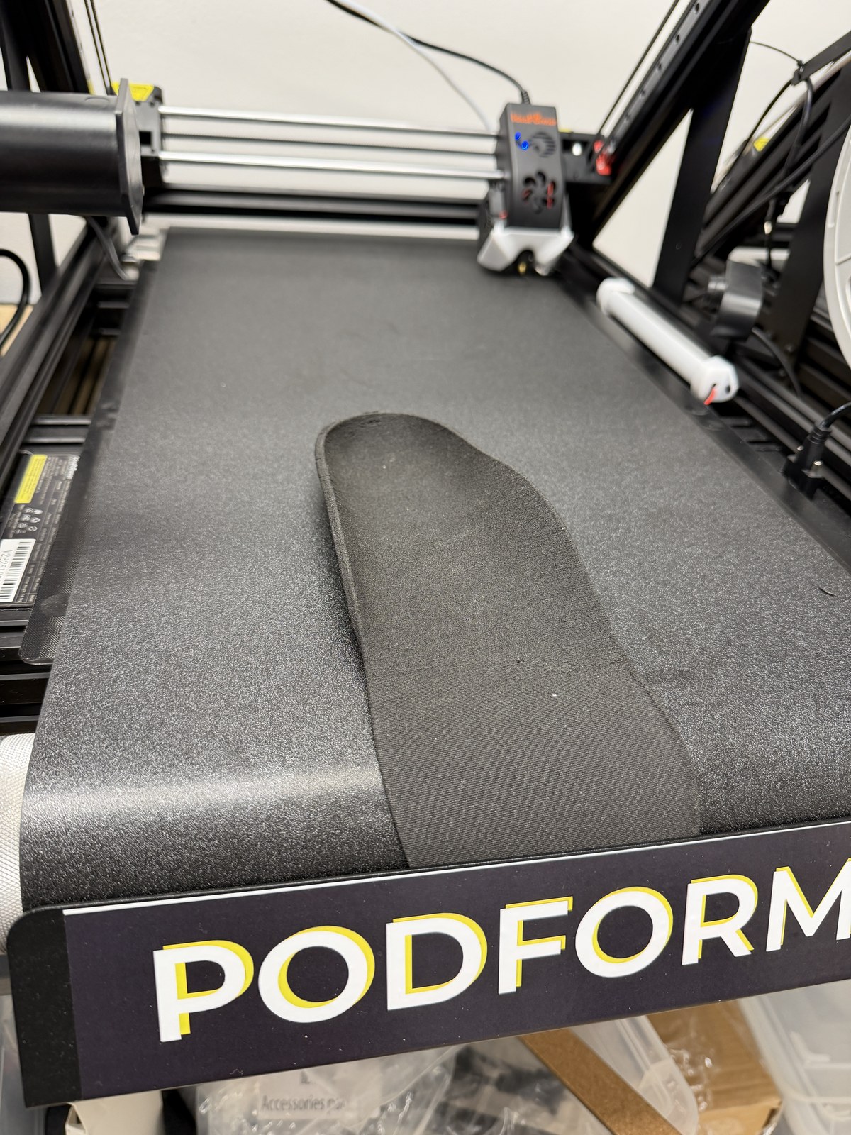
WARNING: this damaged insole is the direct consequence of a baffle gap that is too large. A large gap can let the insole catch or drag and damage the printer. Tighten and recheck
Tighten only after the paper barely passes and there is no visible gap. Recheck after tightening. Do not copy the visible-gap setup shown in the red-X image.
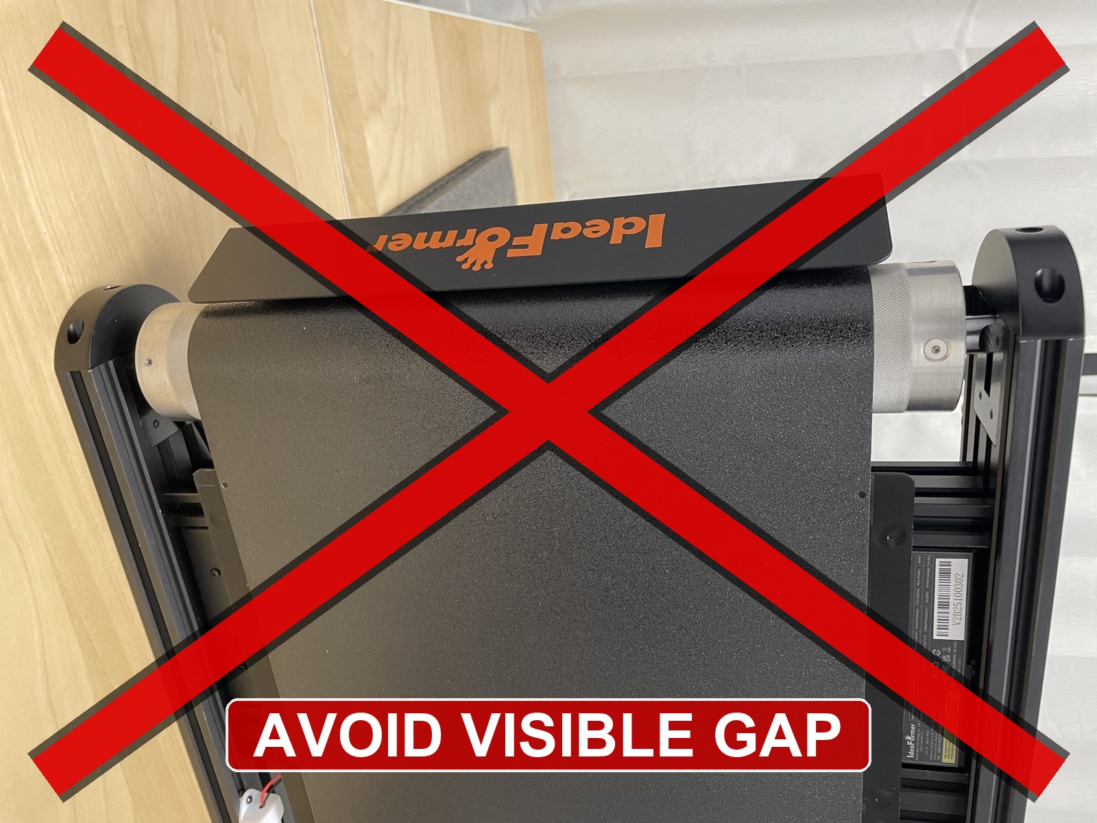
Avoid this visible gap. Reposition the baffle until there is no visible gap and a single sheet of paper barely passes.
Before you finish
- The baffle sits evenly.
- No visible gap remains between the baffle and the belt path.
- A single sheet of paper barely passes across the gap.
- No scraping is visible or audible.
Install the frame squarely
Attach the side supports with the printer flat on the table
Keep the printer flat on the table. If the screw type is unclear, check the manual before tightening.
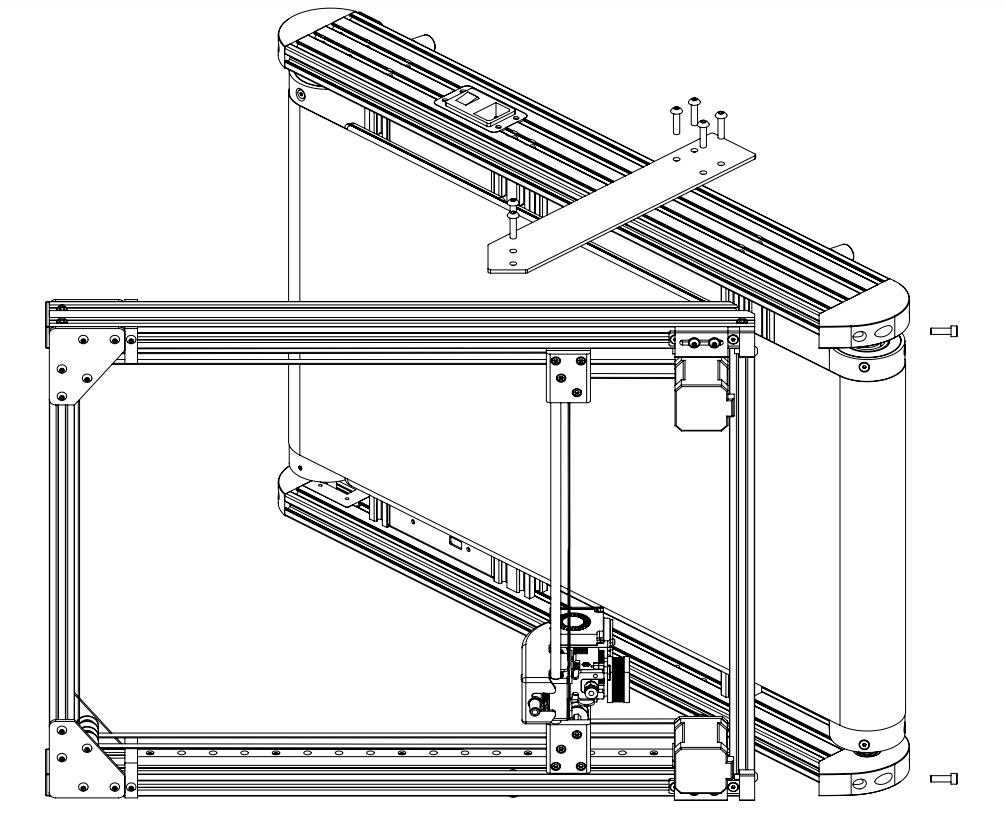
Manual reference for the side-support mounting location. 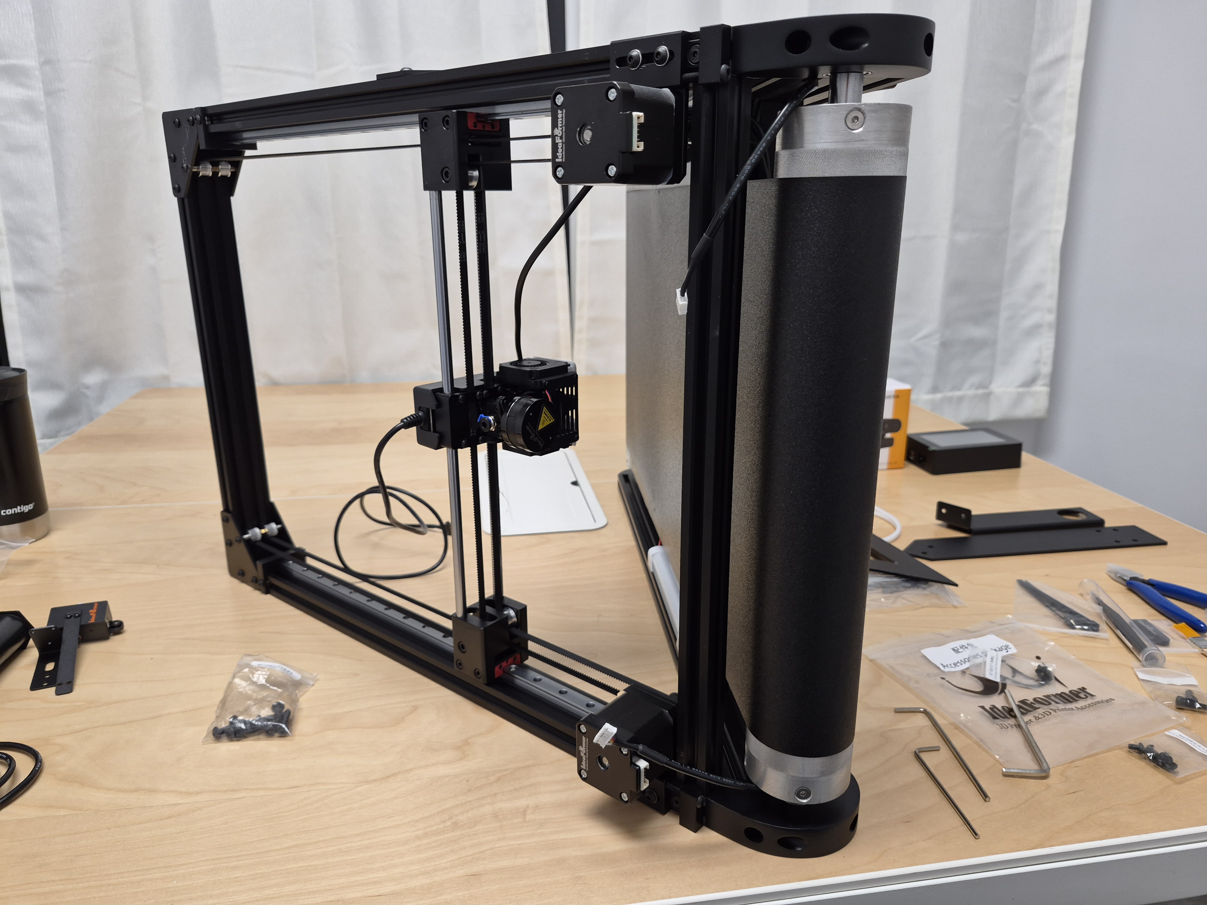
Wide real-world reference that keeps the printer orientation easy to read while the frame is being assembled. Lower the top frame evenly
Lower the top frame evenly so the corners meet without force.
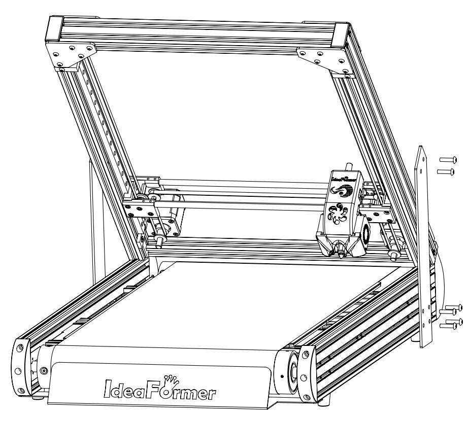
Manual reference for the top-frame attachment sequence. 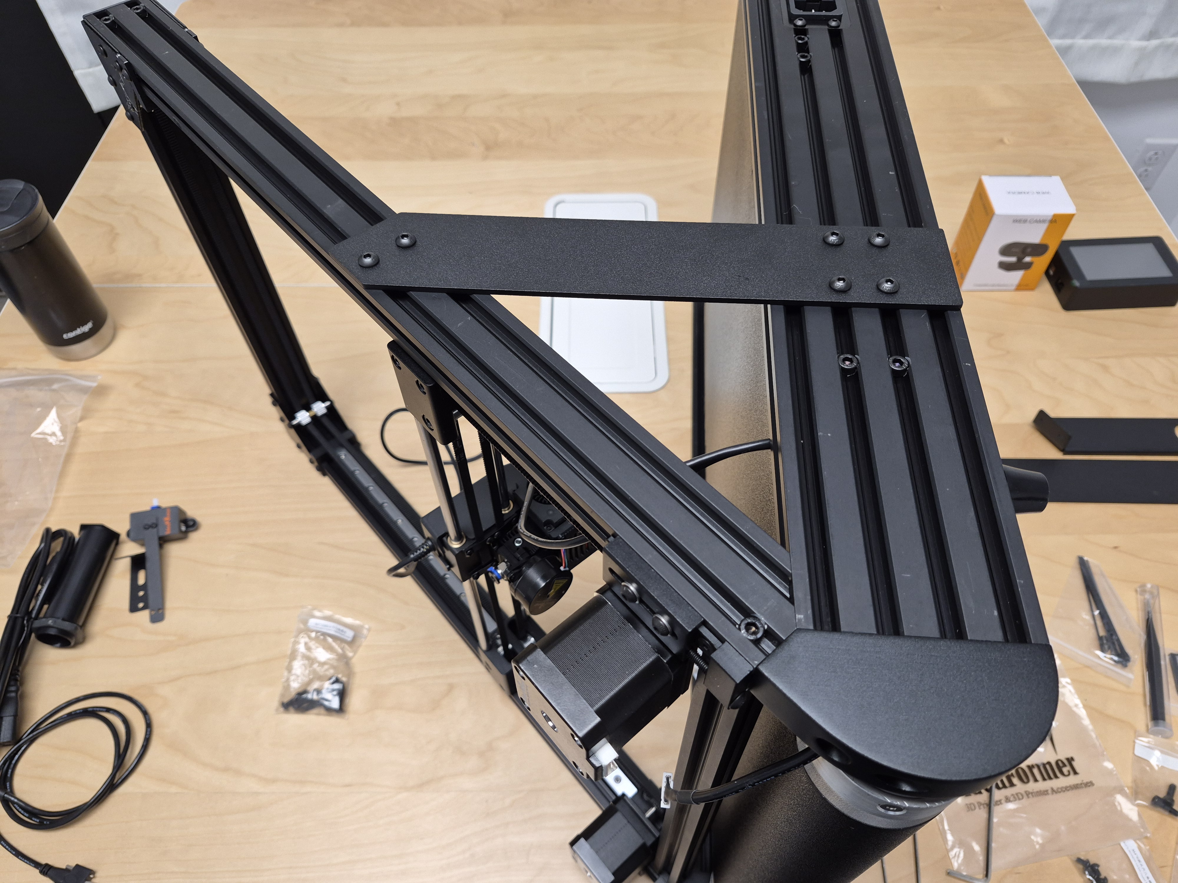
Top-side real-world reference for how the frame should read once the upper structure is aligned. Check the lower attachment points
Check the lower attachment points before final tightening.
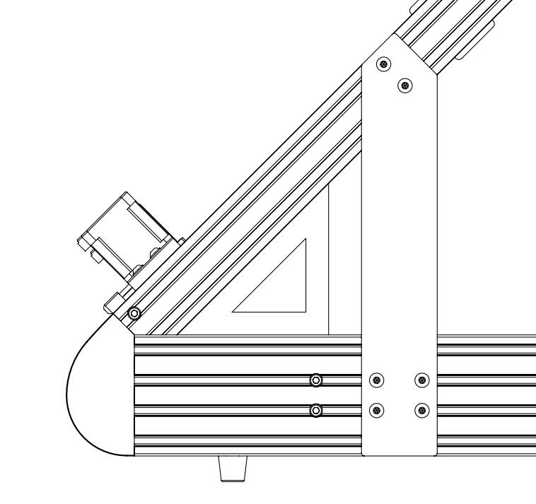
Manual angle-check reference for the lower attachment geometry. 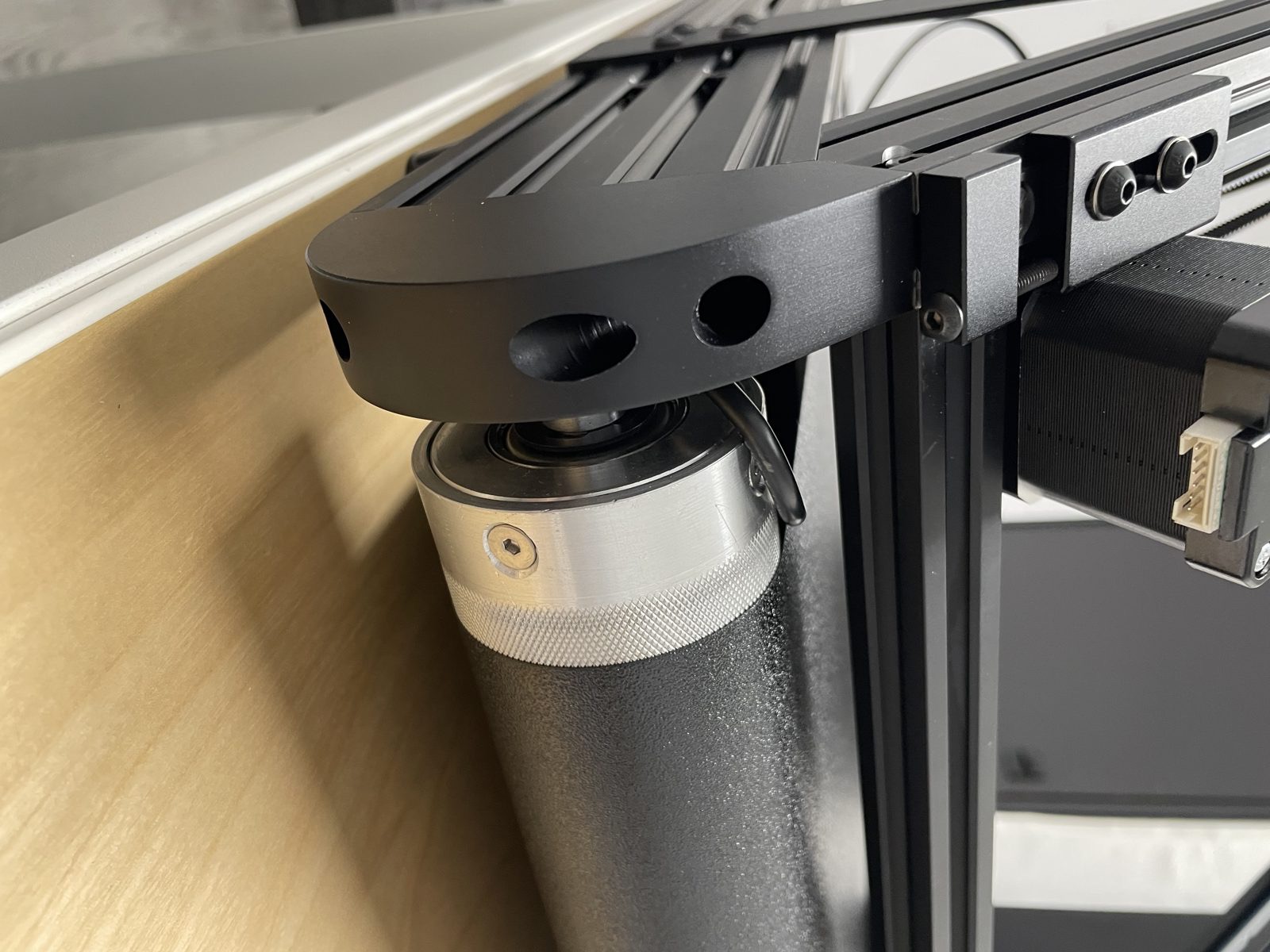
Close-up reference for the lower base attachment area before final tightening. Recheck the print-head position
If the print head looks offset over the belt, realign the frame before continuing.
Before you finish
- The frame is square.
- The lower and upper fasteners are seated.
- The print-head position over the belt still looks normal.
Mount the screen and spool holder
Mount the touchscreen
The screen should be stable, easy to read, and still easy to access from the rear for wiring.
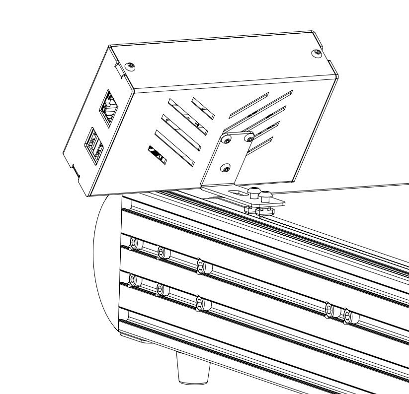
Manual reference for the touchscreen mount. 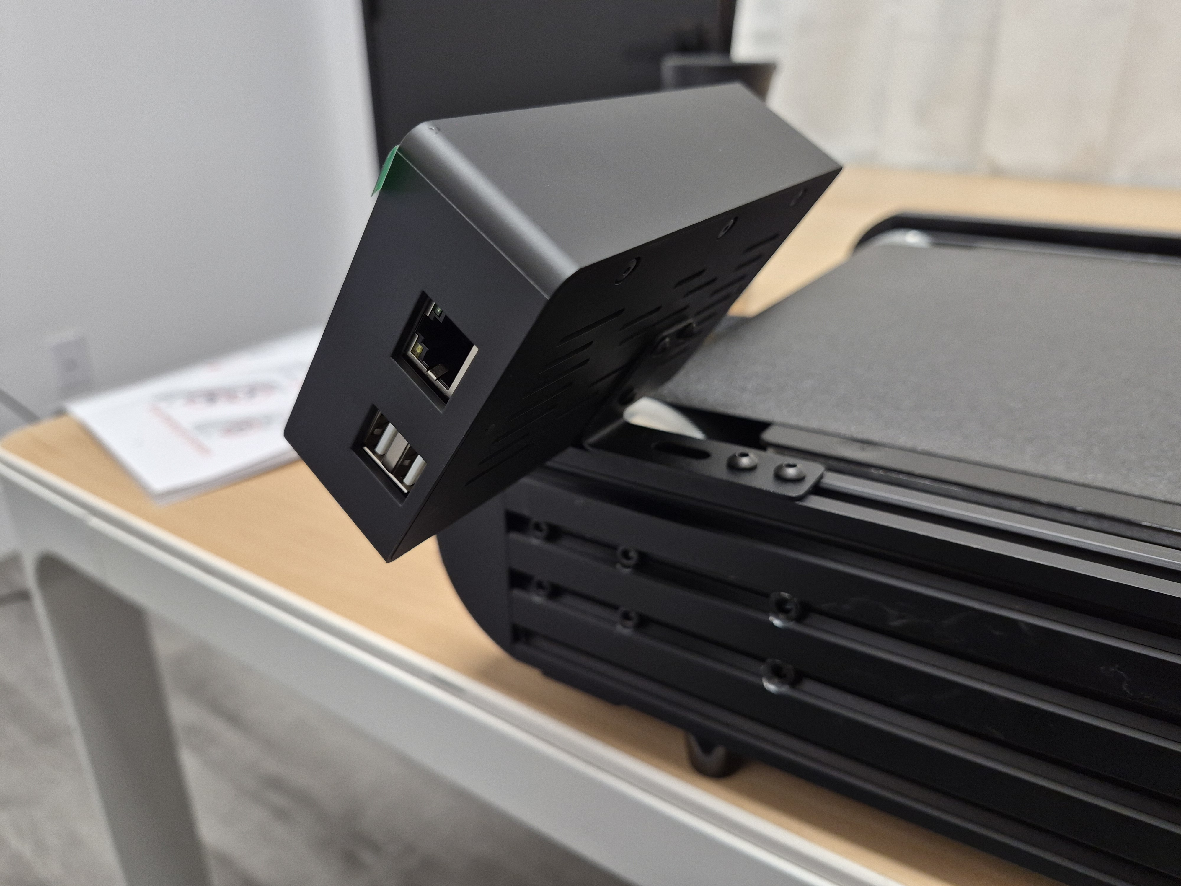
Real-world reference that shows the rear ports still reachable after the screen is mounted. Install the spool holder in line with the feed path
Keep the spool path straight so the later sensor and PTFE routing stay simple.
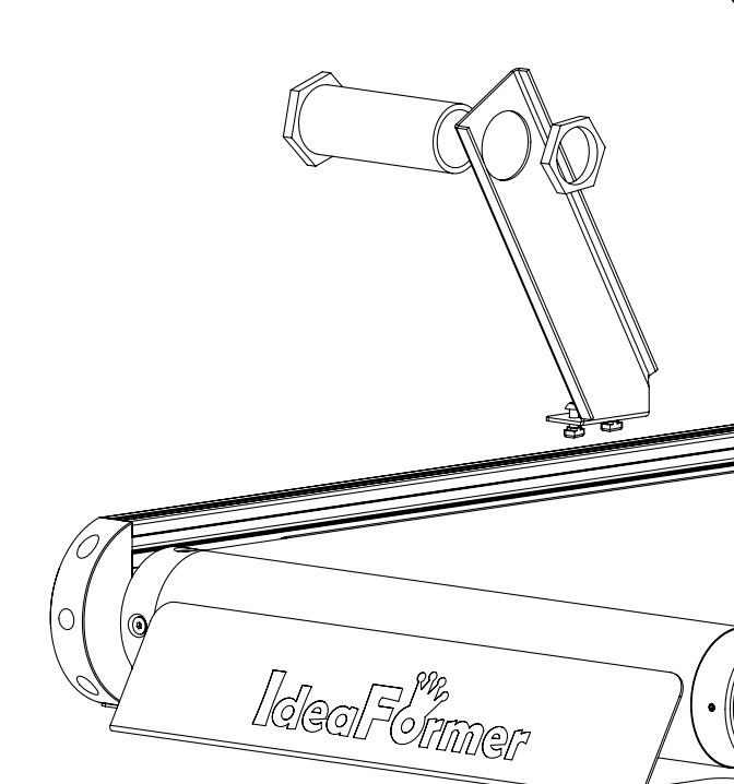
Manual reference for the filament-holder position. 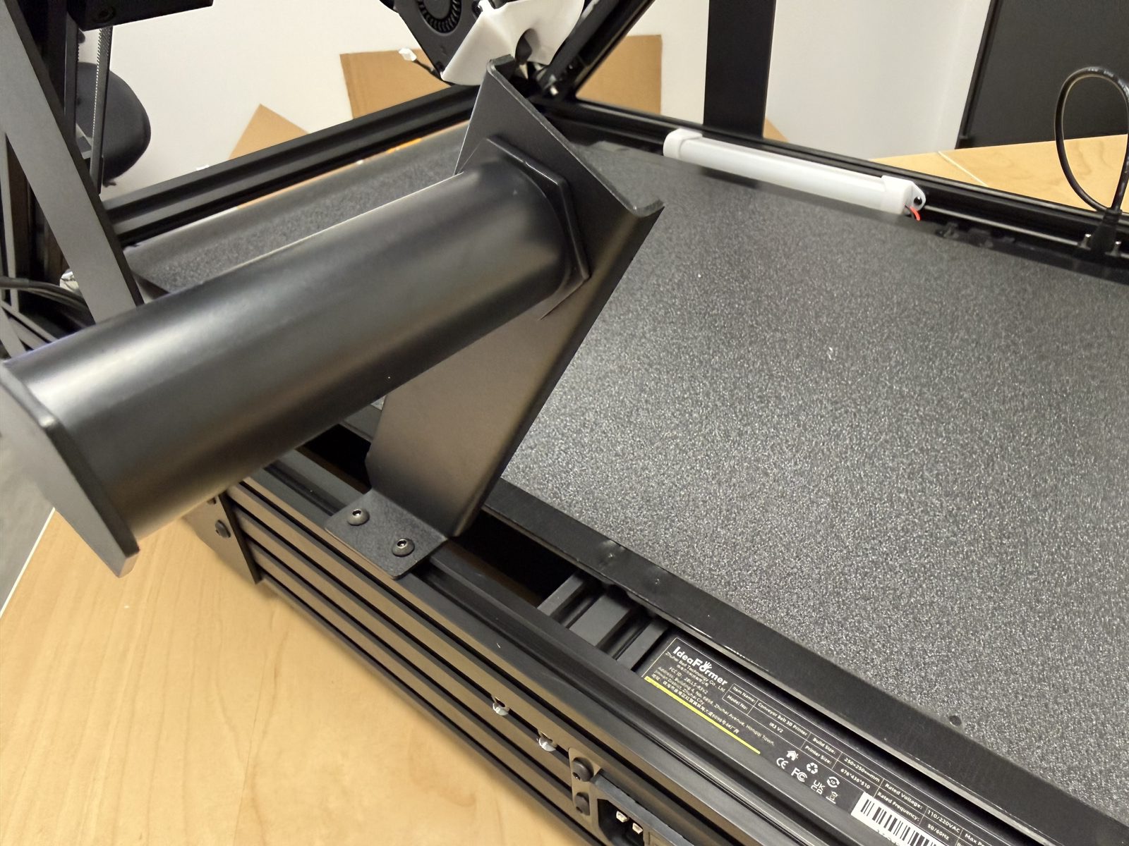
Side-view confirmation of the installed filament-holder position.
Before you finish
- The screen is stable and readable.
- The rear ports are accessible.
- The filament holder is installed and aligned.
Mount the sensor and PTFE tube
Connect the sensor cable first
Plug the cable in while the sensor is still easy to reach.
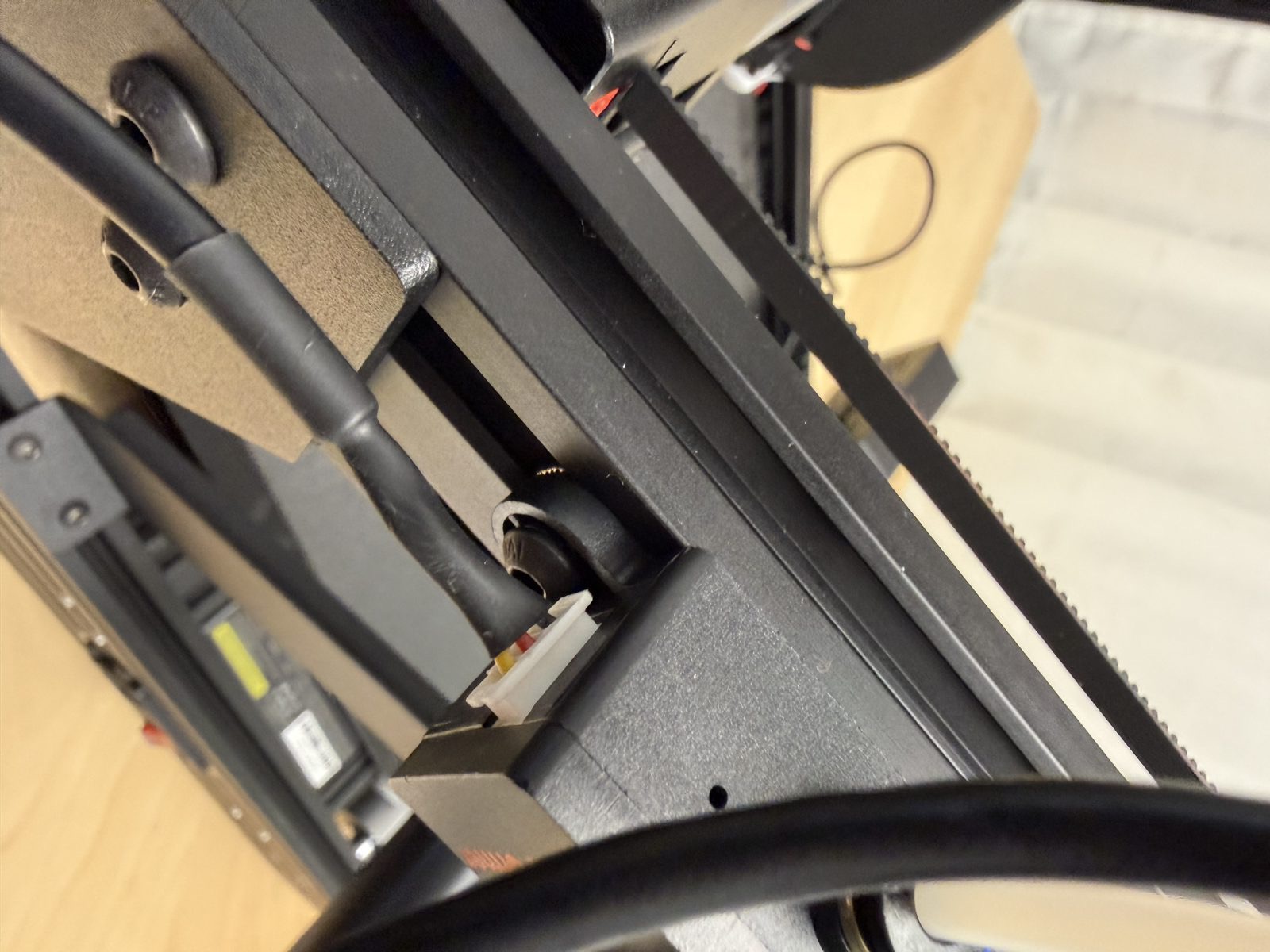
Close-up reference for the sensor cable connection before the final mount. Mount the sensor in the shown orientation
Use the reference images so the feed direction is clear before you tighten it.
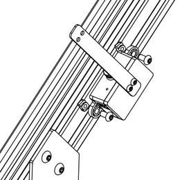
Manual reference for the sensor mount on the rail. 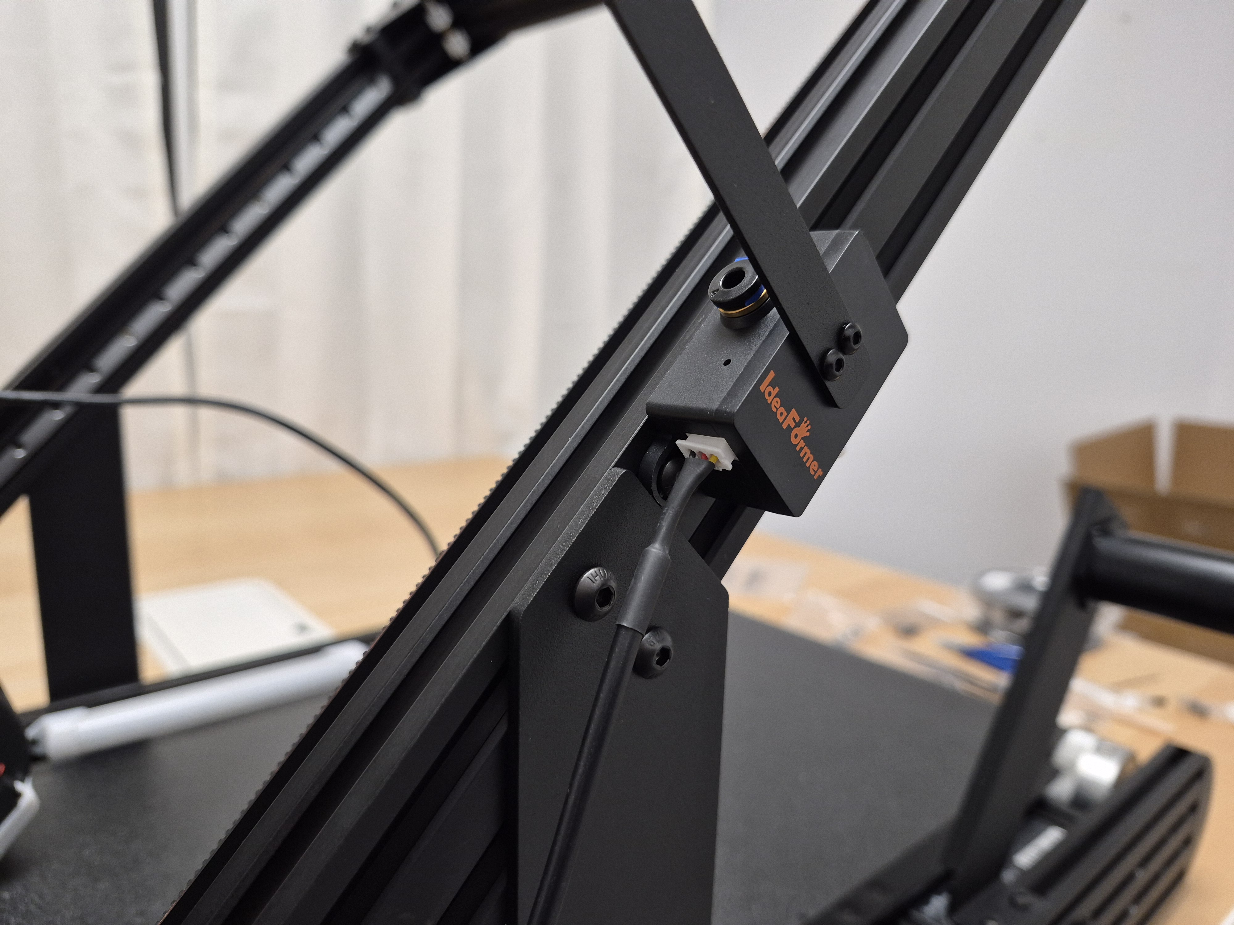
Real-world reference for the installed sensor orientation and cable exit direction. Route the PTFE tube with a wide bend
Avoid sharp bends or crushing. The tube should guide the filament with low friction.
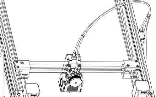
Manual reference for the intended PTFE path into the print head. 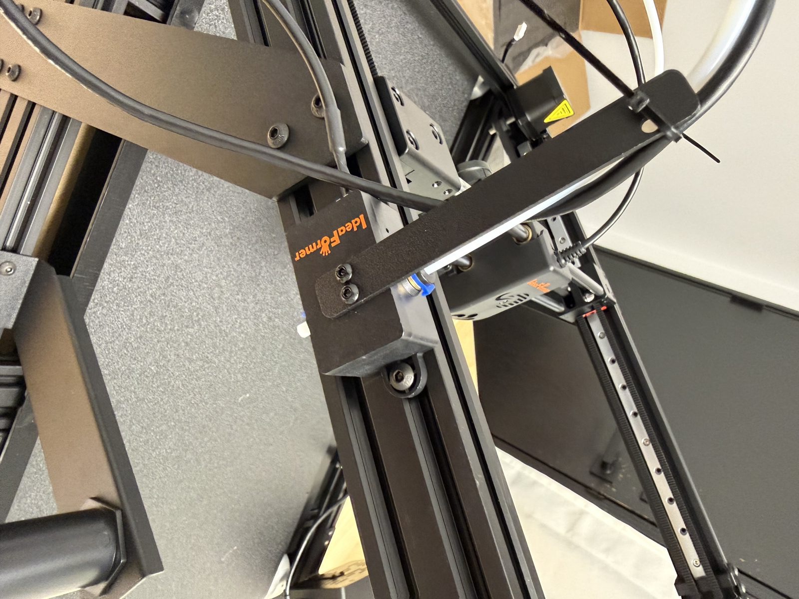
Installed reference showing the PTFE tube seated in the motion sensor fitting.
Before you finish
- The sensor cable is fully seated.
- The sensor orientation is clear.
- The PTFE tube has slack and no kink.
Connect the wiring
Start from the full routing view
Check the full routing view before you connect anything.
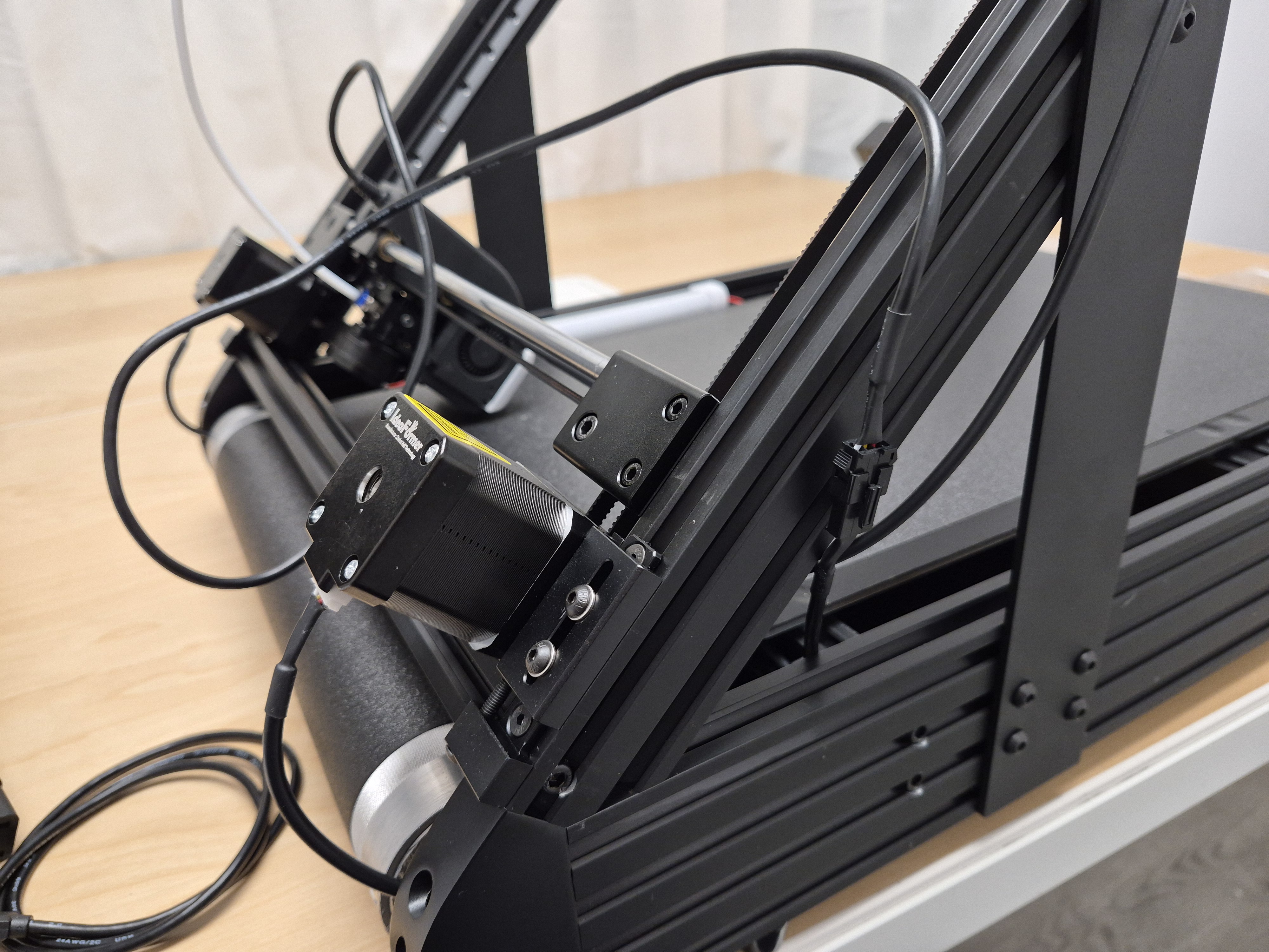
Whole-machine routing reference used before checking the individual connectors. Connect the print-head and motor cables
Fully seat the keyed print-head cable and the X and Y motor cables.
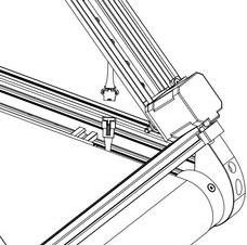
Manual reference for the black print-head cable connection. 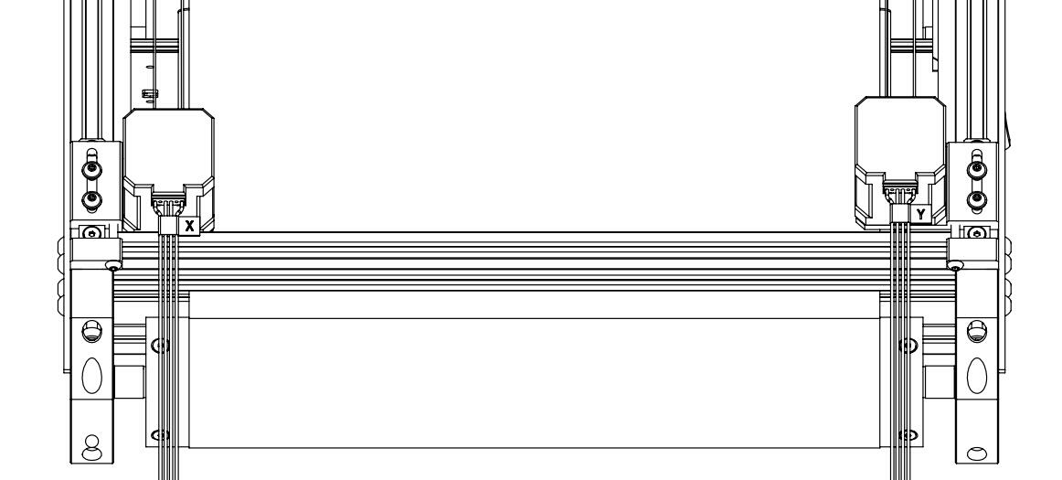
Manual reference for the left and right motor cable connection points. 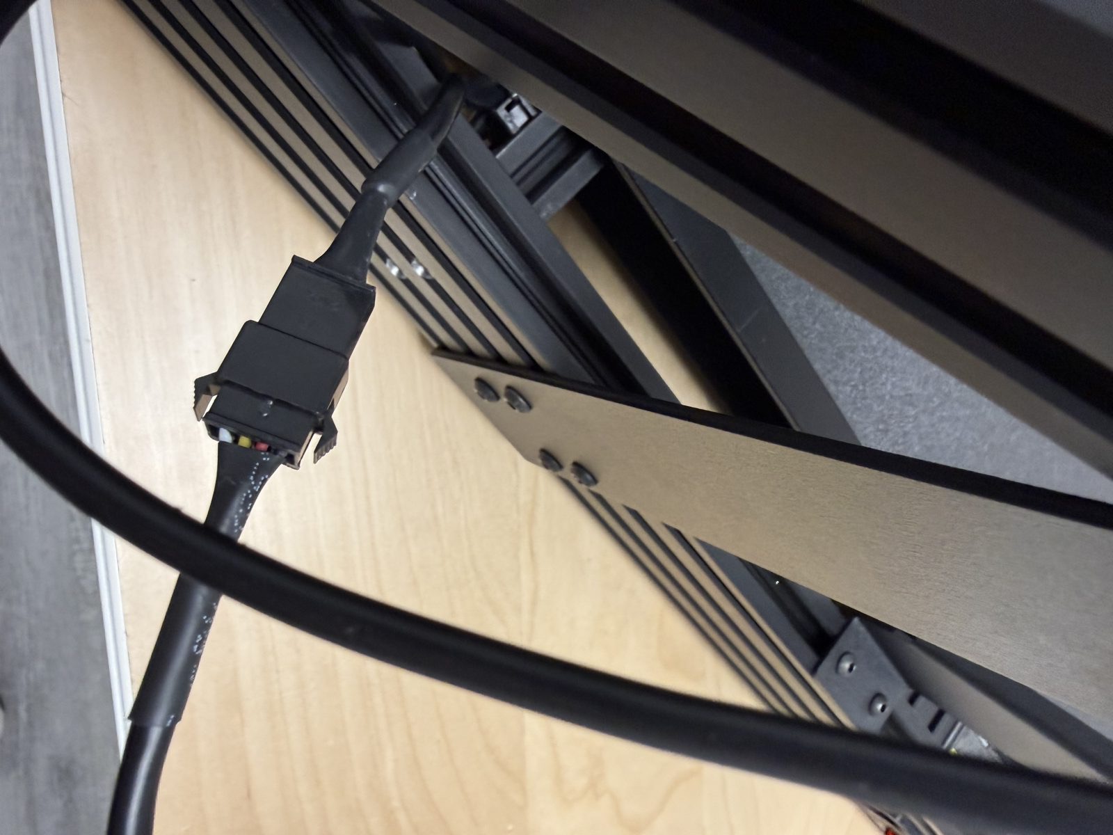
Real-world close-up of the print-head cable seated correctly. 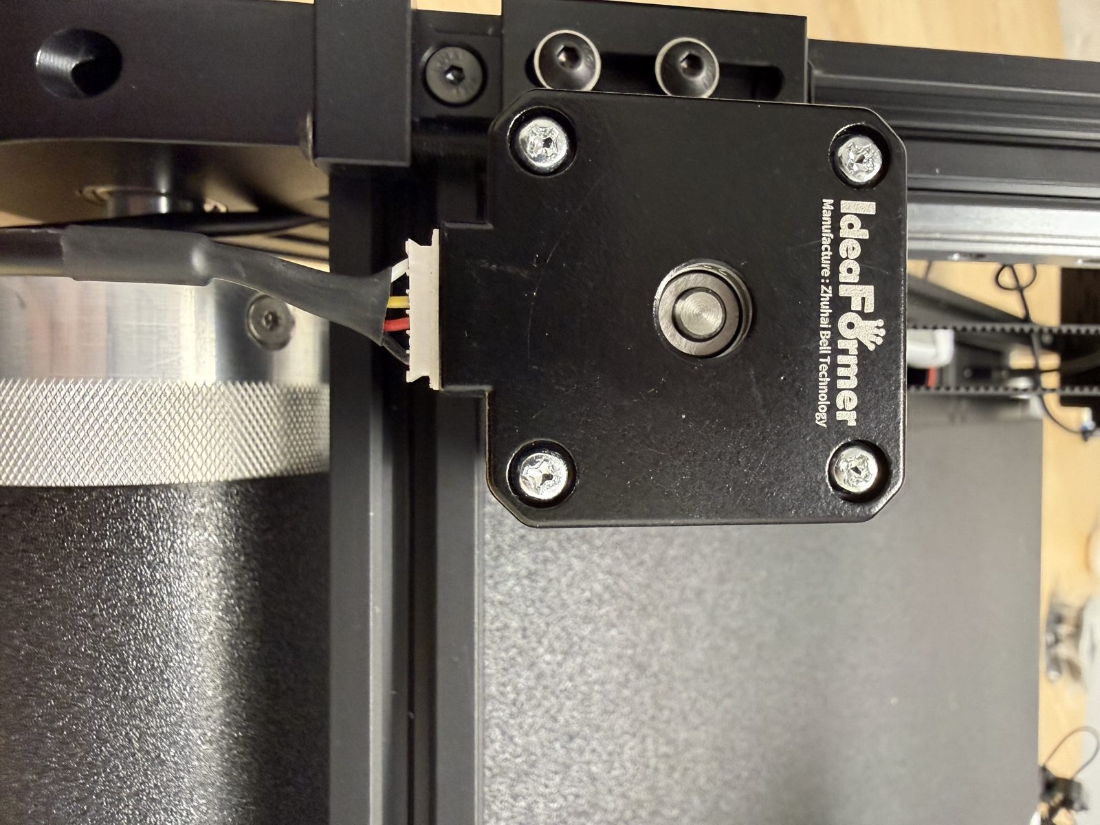
Real-world motor-connection close-up used to verify the keyed fit. Connect the screen and secure the final route
Connect the screen at both ends, then tie the print-head cable to the PTFE tube so nothing hangs in the motion path.
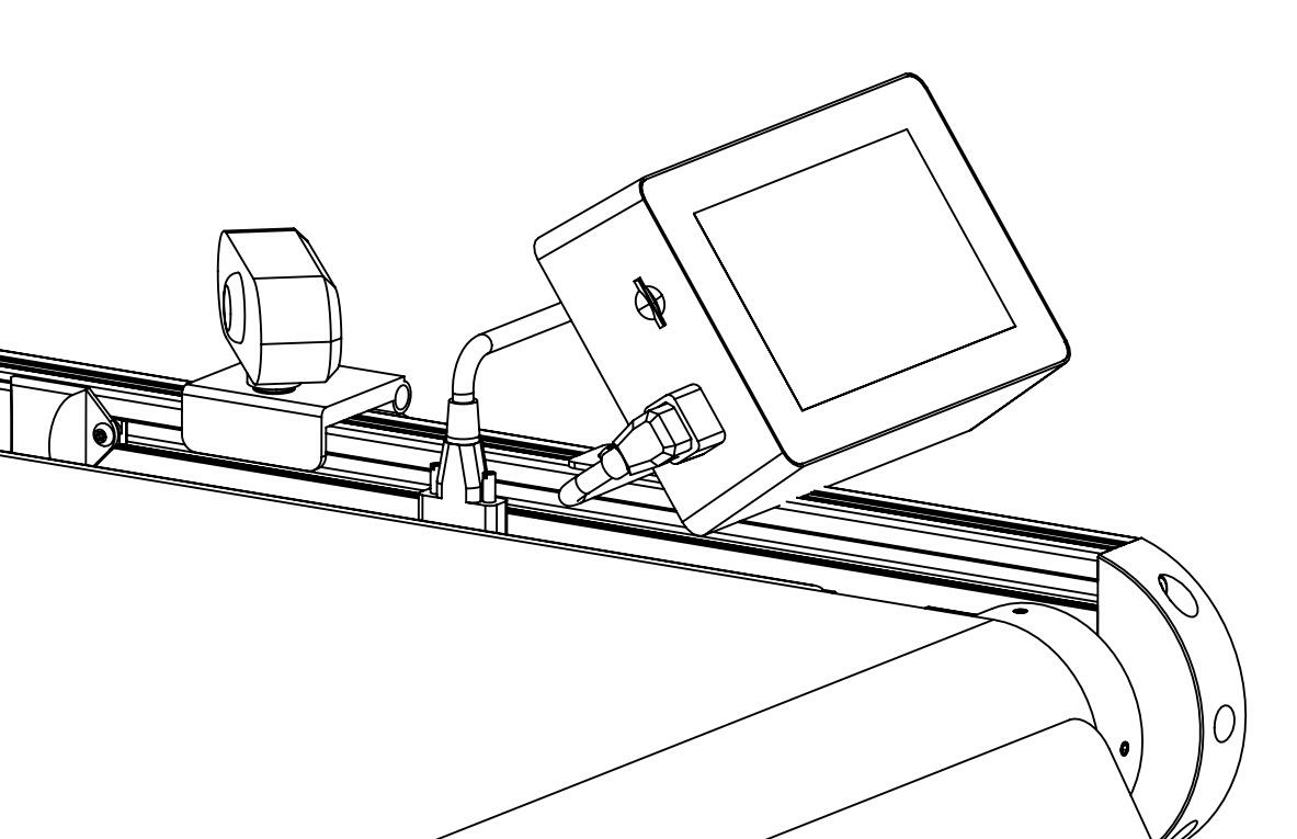
Manual reference for the screen cable connection on the printer side. 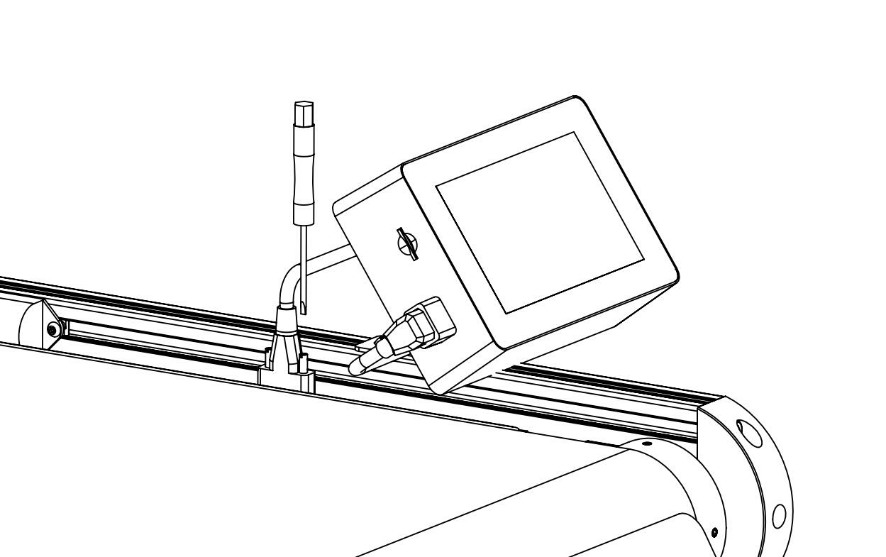
Manual reference for the screen cable connection at the display side.
Before you finish
- The print-head, motor, and screen connectors are seated.
- The print-head cable is secured to the PTFE path.
- Nothing hangs into the motion path.
Mount the camera
Connect the camera USB
Seat the cable fully and leave enough slack for final positioning.
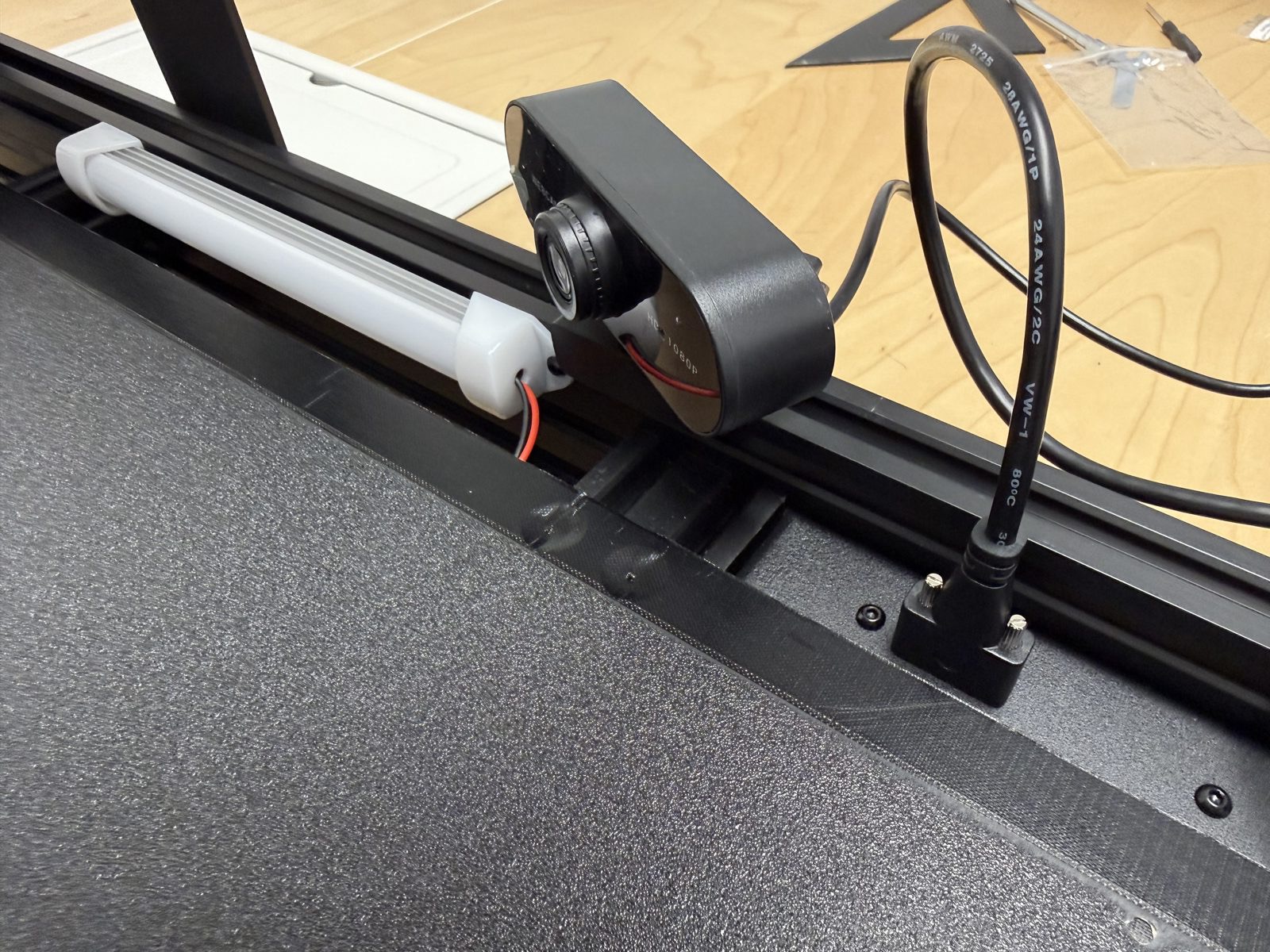
USB connection reference for the camera before final mounting. Mount the camera under the rail
Aim for a stable mount, clear view, and no cable interference.
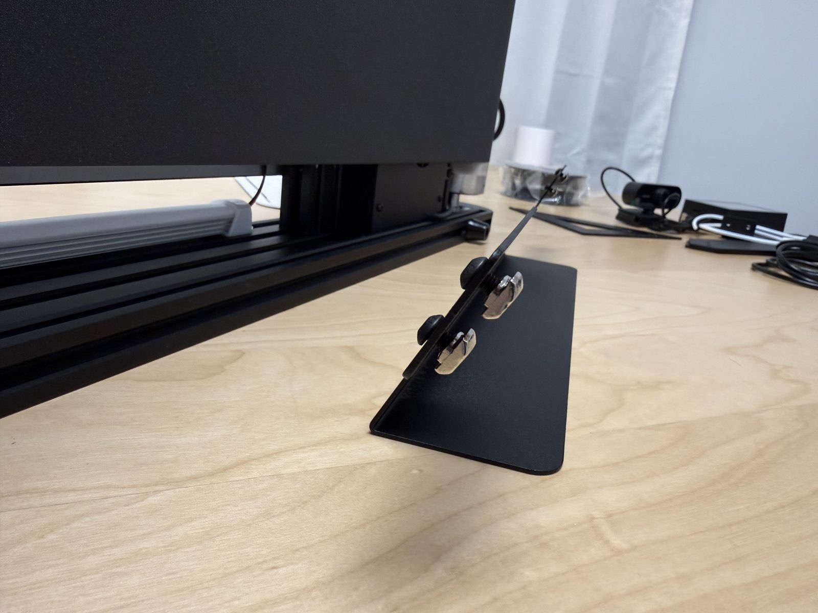
Reference position for the camera under the rail. 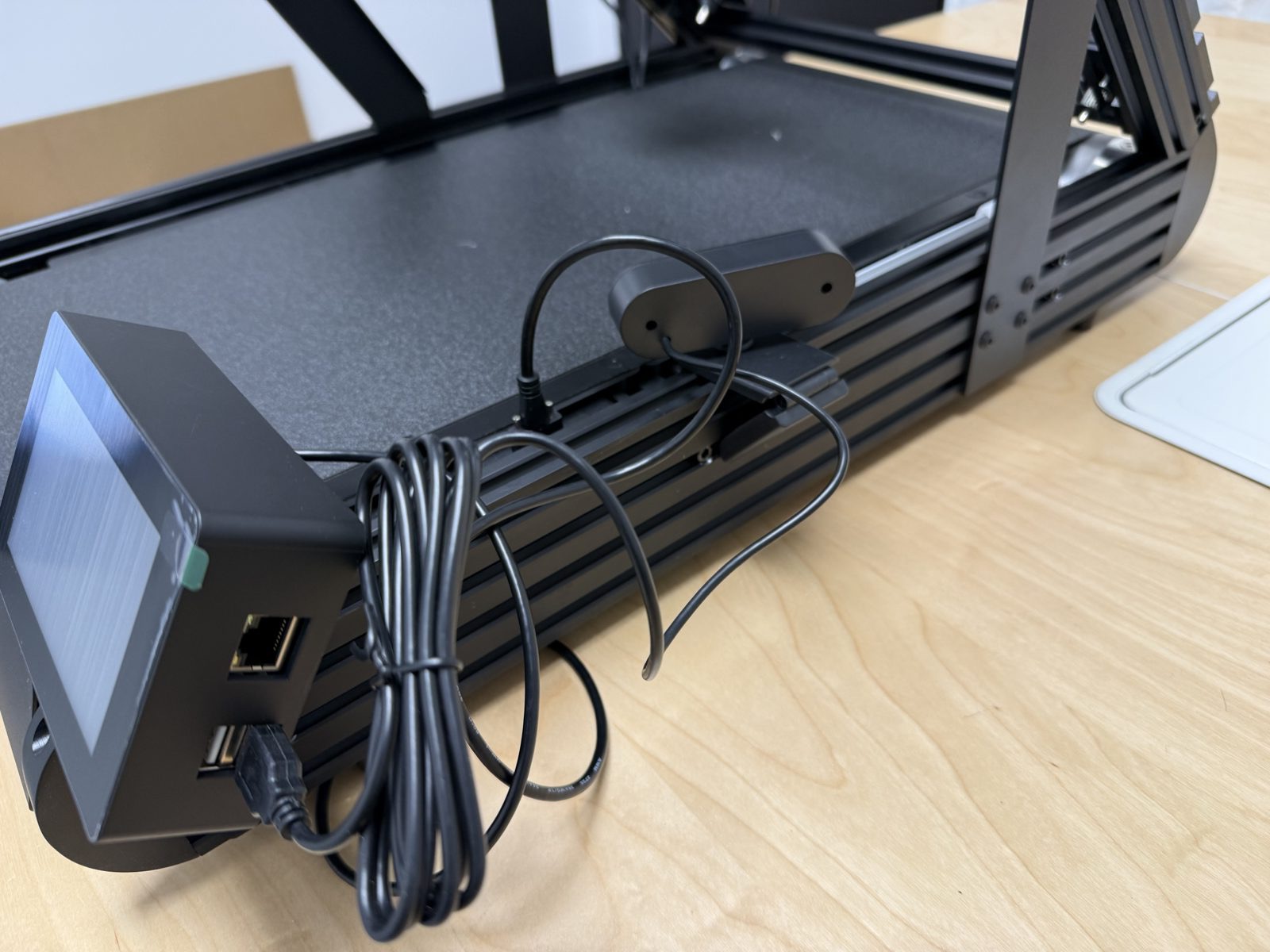
Final under-screen view used to confirm the camera position relative to the screen.
Before you finish
- The camera cable is connected.
- The mount is stable.
- The screen and camera arrangement matches the reference.
Pre-Power-On Validation
Run the final pre-power check
Scan the machine from top to bottom
Compare the build to the reference and look for anything out of place.
Manual overview used for the whole-machine pre-power reference. 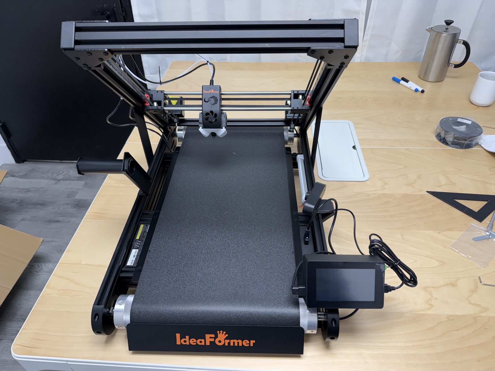
Top-down real-world reference used before the first power-on. Check fasteners, accessories, and cable paths
Make sure the frame, screen, holder, sensor, PTFE tube, wiring, and camera are secure. Keep every cable out of hot or moving areas.
Stop if anything looks improvised
Do not power the printer if any part still looks loose, forced, or badly routed.
Power on the printer
If everything is correct, power on the printer and continue to Internet Connectivity.
Before you finish
- The machine looks complete and organized.
- Nothing is loose.
- No cable enters a moving or hot path.
- The printer is powered on and ready for Internet Connectivity Setup.